Skip to content
doubtly
Topic: p-n junction diode I-V characteristics· Electronic Devices

The given circuit has two ideal diodes connected as shown in the figure below. The current flowing through the resistance R_1 will be

The given circuit has two ideal diodes connected as shown in the figure below. The current flowing through the resistance \(R_1\) will be
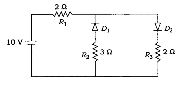
10 V source, R1=2 ohm, diodes D1,D2 with R2=3 ohm, R3=2 ohm

1. 10.0 A

2. 1.43 A

3. 3.13 A

4. 2.5 A

1 answer

Best answer

Answer: 4. 2.5 A

An ideal diode conducts only when forward biased. From the figure, the battery drives current through \(R_1\) and then to the two diode branches.

  • \(D_1\) (with \(R_2\)) is connected the opposite way, so it is reverse biased and carries no current.
  • \(D_2\) (with \(R_3\)) is forward biased and acts as a plain wire.

The circuit is 10 V across \(R_1+R_3=2+2=4\ \Omega\).

$$I=\frac{10}{4}=2.5\ \text{A}$$

Option (4).

Doubtly AI · 30 Oct 2026 AI-generated · not yet verified Report
Was this answer helpful?

Your answer

Log in or create a free account to answer this question.