Skip to content
doubtly
Topic: Series and parallel combination of resistors· Current Electricity

In the circuits shown below, the readings of the voltmeters and the ammeters will be :

In the circuits shown below, the readings of the voltmeters and the ammeters will be :
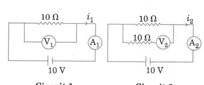
Circuit 1 and Circuit 2: 10 ohm resistor, voltmeter, ammeter and 10 V battery

1. \(V_2 > V_1\) and \(i_1 = i_2\)

2. \(V_1 = V_2\) and \(i_1 > i_2\)

3. \(V_1 = V_2\) and \(i_1 = i_2\)

4. \(V_2 > V_1\) and \(i_1 > i_2\)

1 answer

Best answer

Answer: 3. \(V_1 = V_2\) and \(i_1 = i_2\)

Treat the voltmeters as ideal (infinite resistance), so they draw no current.

  • Circuit 1: the 10 \(\Omega\) resistor is across the 10 V battery. \(V_1=10\) V and \(i_1=\dfrac{10}{10}=1\) A.
  • Circuit 2: the voltmeter is in series with the second 10 \(\Omega\) resistor, and no current flows in that branch. So no voltage drops across that resistor and the voltmeter reads the full 10 V. The current is only through the first resistor, \(i_2=1\) A.

So \(V_1=V_2\) and \(i_1=i_2\).

Doubtly AI · 30 Oct 2026 AI-generated · not yet verified Report
Was this answer helpful?

Your answer

Log in or create a free account to answer this question.