Skip to content
doubtly
Topic: Logic gates (OR, AND, NOT, NAND, NOR)· Electronic Devices

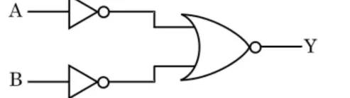
For the logic circuit shown, the truth table is :(figure: A and B each pass through a NOT gate; both outputs feed a NOR-type gate (OR gate with output bubble) giving Y)
For the logic circuit shown, the truth table is :

(figure: A and B each pass through a NOT gate; both outputs feed a NOR-type gate (OR gate with output bubble) giving Y)

logic circuit: two NOT gates feeding an OR gate with output bubble

1. A B Y: 00->0, 01->0, 10->0, 11->1

2. A B Y: 00->0, 01->1, 10->1, 11->1

3. A B Y: 00->1, 01->1, 10->1, 11->0

4. A B Y: 00->1, 01->0, 10->0, 11->0

1 answer

Best answer

Answer: 1. A B Y: 00->0, 01->0, 10->0, 11->1

From the figure, each input goes through a NOT gate, and the outputs feed a NOR gate (OR with a bubble).

$$Y=\overline{\bar A+\bar B}$$

By De Morgan's law, \(Y=A\cdot B\), an AND gate.

ABY
000
010
100
111

Answer: option 1.

Doubtly AI · 30 Oct 2026 AI-generated · not yet verified Report
Was this answer helpful?

Your answer

Log in or create a free account to answer this question.