Skip to content
doubtly

Logic gates (OR, AND, NOT, NAND, NOR)

12 solved questions

Every question from past board papers on Logic gates (OR, AND, NOT, NAND, NOR), newest paper first. Open any question for its full worked answer.

NEET UG 2025 question paper (official, booklet 45)

Full paper →
  1. The output (Y) of the given logic implementation is similar to the output of an/a ________ gate.
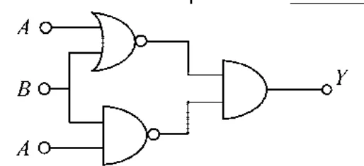
    logic circuit: inputs A,B,A; OR-bubble gate (NOR) and NAND-type bubble gate feeding an AND gate giving Y

    4 marks · See worked answer →

NEET UG 2024 question paper (official, booklet S6)

Full paper →
  1. The output (\(Y\)) of the given logic gate is similar to the output of an/a :
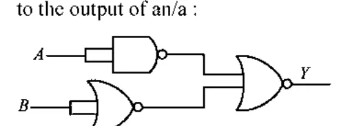
    logic circuit with NAND and NOR feeding an OR-type gate

    4 marks · See worked answer →

  2. A logic circuit provides the output \(Y\) as per the following truth table :

    | A | B | Y |

    |---|---|---|

    | 0 | 0 | 1 |

    | 0 | 1 | 0 |

    | 1 | 0 | 1 |

    | 1 | 1 | 0 |

    The expression for the output \(Y\) is :

    4 marks · See worked answer →

NEET UG 2023 question paper (official, booklet G6)

Full paper →
  1. For the following logic circuit, the truth table is:
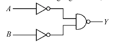
    A and B each through a NOT gate, outputs into a NAND gate giving Y

    4 marks · See worked answer →

NEET UG 2022 question paper (official, booklet R6)

Full paper →
  1. The truth table for the given logic circuit is :
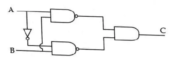
    logic circuit with diode, two NAND gates and an AND-type gate, inputs A,B output C

    4 marks · See worked answer →

NEET UG 2021 question paper (official, booklet M4)

Full paper →
  1. For the given circuit, the input digital signals are applied at the terminals A, B and C. What would be the output at the terminal y ?
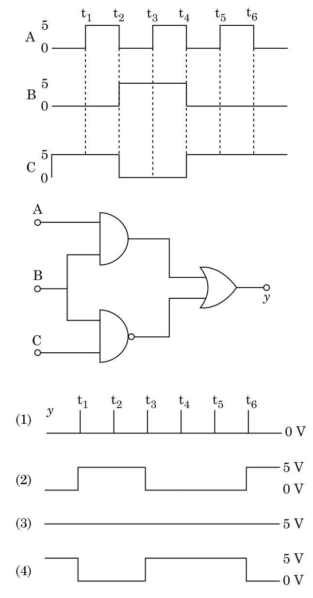
    input waveforms A, B, C; logic circuit with AND, NAND, OR gates; four output waveform options

    4 marks · See worked answer →

NEET UG 2020 question paper (official, booklet E1)

Full paper →
  1. For the logic circuit shown, the truth table is :

    (figure: A and B each pass through a NOT gate; both outputs feed a NOR-type gate (OR gate with output bubble) giving Y)
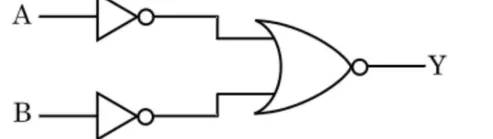
    logic circuit: two NOT gates feeding an OR gate with output bubble

    4 marks · See worked answer →

NEET UG 2019 question paper (official, booklet P1)

Full paper →
  1. The correct Boolean operation represented by the circuit diagram drawn is :
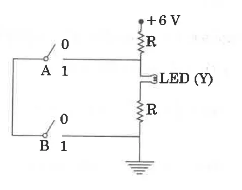
    switch circuit with +6V, two resistors R, LED(Y), switches A and B

    4 marks · See worked answer →

NEET UG 2018 question paper (official, booklet EE)

Full paper →
  1. In the combination of the following gates the output Y can be written in terms of inputs A and B as
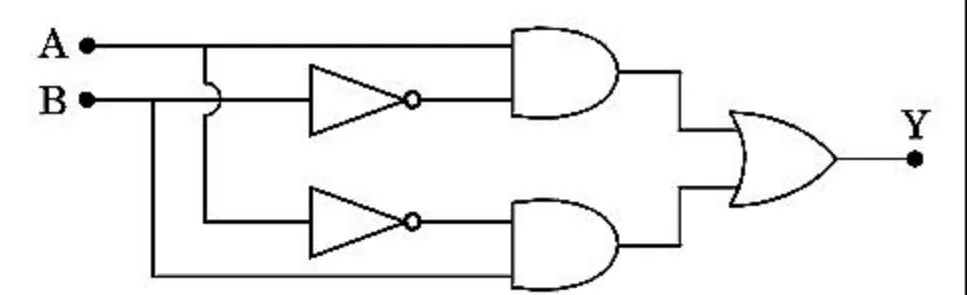
    logic gate network (NOT, AND, OR)

    4 marks · See worked answer →

NEET UG 2017 question paper (official, booklet B)

Full paper →
  1. The given electrical network is equivalent to :
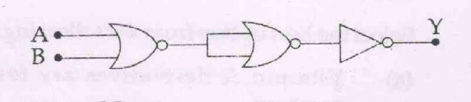
    logic network: inputs A,B into OR gate, then NOT-type gate stages to output Y

    4 marks · See worked answer →

NEET UG 2016 Phase 1 question paper (official, booklet A)

Full paper →
  1. To get output 1 for the following circuit, the correct choice for the input is :
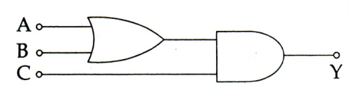
    logic circuit: inputs A,B into OR gate, its output and C into AND gate, output Y

    4 marks · See worked answer →

NEET UG 2016 Phase 2 question paper (official, booklet ZZ)

Full paper →
  1. What is the output \(Y\) in the following circuit, when all the three inputs \(A, B, C\) are first 0 and then 1?

    gate P (A,B inputs) feeding gate Q with C to output Y

    4 marks · See worked answer →