
AB is a part of an electrical circuit (see figure). The potential difference "\(V_A - V_B\)", at the instant when current i = 2 A and is increasing at a rate of 1 amp / second is:

Every question from past board papers on Electromagnetic Induction and Alternating Currents, newest paper first. Open any question for its full worked answer.
AB is a part of an electrical circuit (see figure). The potential difference "\(V_A - V_B\)", at the instant when current i = 2 A and is increasing at a rate of 1 amp / second is:
To an ac power supply of 220 V at 50 Hz, a resistor of 20 \(\Omega\), a capacitor of reactance 25 \(\Omega\) and an inductor of reactance 45 \(\Omega\) are connected in series. The corresponding current in the circuit and the phase angle between the current and the voltage is, respectively -
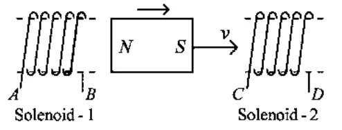
In the above diagram, a strong bar magnet is moving towards solenoid-2 from solenoid-1. The direction of induced current in solenoid-1 and that in solenoid-2, respectively, are through the directions:
In an ideal transformer, the turns ratio is \(\frac{N_p}{N_s}=\frac{1}{2}\). The ratio \(V_s : V_p\) is equal to (the symbols carry their usual meaning) :
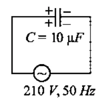
A 10 \(\mu F\) capacitor is connected to a 210 V, 50 Hz source as shown in figure. The peak current in the circuit is nearly (\(\pi=3.14\)):
A sheet is placed on a horizontal surface in front of a strong magnetic pole. A force is needed to :
A. hold the sheet there if it is magnetic.
B. hold the sheet there if it is non-magnetic.
C. move the sheet away from the pole with uniform velocity if it is conducting.
D. move the sheet away from the pole with uniform velocity if it is both, non-conducting and non-polar.
Choose the correct statement(s) from the options given below:
A 12 V, 60 W lamp is connected to the secondary of a step down transformer, whose primary is connected to ac mains of 220 V. Assuming the transformer to be ideal, what is the current in the primary winding?
The magnetic energy stored in an inductor of inductance \(4\,\mu\mathrm{H}\) carrying a current of 2 A is :
In a series \(LCR\) circuit, the inductance \(L\) is 10 mH, capacitance \(C\) is \(1\,\mu\)F and resistance \(R\) is \(100\,\Omega\). The frequency at which resonance occurs is :
An ac source is connected to a capacitor C. Due to decrease in its operating frequency :
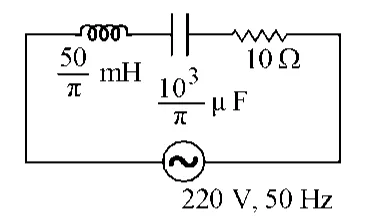
The net impedance of circuit (as shown in figure) will be :
The peak voltage of the ac source is equal to :
A square loop of side 1 m and resistance \(1\,\Omega\) is placed in a magnetic field of 0.5 T. If the plane of loop is perpendicular to the direction of magnetic field, the magnetic flux through the loop is :
A series LCR circuit with inductance 10 H, capacitance 10 \(\mu\)F, resistance \(50\,\Omega\) is connected to an ac source of voltage, \(V = 200 \sin(100\,t)\) volt. If the resonant frequency of the LCR circuit is \(\nu_0\) and the frequency of the ac source is \(\nu\), then :
A big circular coil of 1000 turns and average radius 10 m is rotating about its horizontal diameter at 2 rad \(\text{s}^{-1}\). If the vertical component of earth's magnetic field at that place is \(2 \times 10^{-5}\) T and electrical resistance of the coil is \(12.56\,\Omega\), then the maximum induced current in the coil will be :
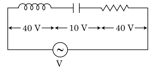
An inductor of inductance L, a capacitor of capacitance C and a resistor of resistance 'R' are connected in series to an ac source of potential difference 'V' volts as shown in figure.
Potential difference across L, C and R is 40 V, 10 V and 40 V, respectively. The amplitude of current flowing through LCR series circuit is \(10\sqrt{2}\) A. The impedance of the circuit is :
Two conducting circular loops of radii \(R_1\) and \(R_2\) are placed in the same plane with their centres coinciding. If \(R_1 >> R_2\), the mutual inductance M between them will be directly proportional to :
A series LCR circuit containing 5.0 H inductor, 80 μF capacitor and 40 Ω resistor is connected to 230 V variable frequency ac source. The angular frequencies of the source at which power transferred to the circuit is half the power at the resonant angular frequency are likely to be :
A step down transformer connected to an ac mains supply of 220 V is made to operate at 11 V, 44 W lamp. Ignoring power losses in the transformer, what is the current in the primary circuit ?
A 40 \(\mu\)F capacitor is connected to a 200 V, 50 Hz ac supply. The rms value of the current in the circuit is, nearly :
A series LCR circuit is connected to an ac voltage source. When L is removed from the circuit, the phase difference between current and voltage is \(\frac{\pi}{3}\). If instead C is removed from the circuit, the phase difference is again \(\frac{\pi}{3}\) between current and voltage. The power factor of the circuit is :
In which of the following devices, the eddy current effect is not used ?
A 800 turn coil of effective area 0.05 m\(^2\) is kept perpendicular to a magnetic field \(5\times10^{-5}\) T. When the plane of the coil is rotated by \(90^\circ\) around any of its coplanar axis in 0.1 s, the emf induced in the coil will be :
An inductor 20 mH, a capacitor 100 \(\mu\)F and a resistor 50 \(\Omega\) are connected in series across a source of emf, V = 10 sin 314 t. The power loss in the circuit is
The magnetic potential energy stored in a certain inductor is 25 mJ, when the current in the inductor is 60 mA. This inductor is of inductance
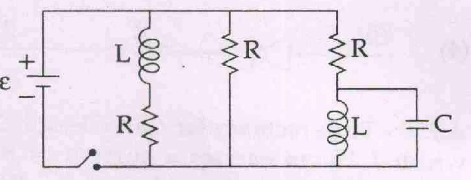
Figure shows a circuit that contains three identical resistors with resistance R = 9.0 \(\Omega\) each, two identical inductors with inductance L = 2.0 mH each, and an ideal battery with emf \(\varepsilon\) = 18 V. The current 'i' through the battery just after the switch closed is,.....
A long solenoid of diameter 0.1 m has \(2\times10^4\) turns per meter. At the centre of the solenoid, a coil of 100 turns and radius 0.01 m is placed with its axis coinciding with the solenoid axis. The current in the solenoid reduces at a constant rate to 0A from 4 A in 0.05 s. If the resistance of the coil is \(10\pi^2\,\Omega\), the total charge flowing through the coil during this time is :
An inductor 20 mH, a capacitor 50 \(\mu\)F and a resistor 40 \(\Omega\) are connected in series across a source of emf \(V = 10 \sin 340\,t\). The power loss in A.C. circuit is :
A long solenoid has 1000 turns. When a current of 4A flows through it, the magnetic flux linked with each turn of the solenoid is \(4\times10^{-3}\) Wb. The self-inductance of the solenoid is :
A small signal voltage \(V(t) = V_0 \sin\omega t\) is applied across an ideal capacitor C :
Which of the following combinations should be selected for better tuning of an \(L\)-\(C\)-\(R\) circuit used for communication?
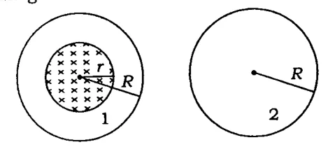
A uniform magnetic field is restricted within a region of radius \(r\). The magnetic field changes with time at a rate \(\frac{d\vec B}{dt}\). Loop 1 of radius \(R>r\) encloses the region \(r\) and loop 2 of radius \(R\) is outside the region of magnetic field as shown in the figure below. Then the e.m.f. generated is
The potential differences across the resistance, capacitance and inductance are 80 V, 40 V and 100 V respectively in an \(L\)-\(C\)-\(R\) circuit. The power factor of this circuit is
A 100 \(\Omega\) resistance and a capacitor of 100 \(\Omega\) reactance are connected in series across a 220 V source. When the capacitor is 50% charged, the peak value of the displacement current is