
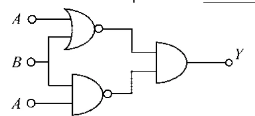
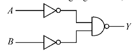
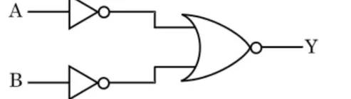
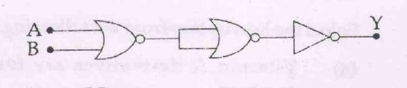
The output (Y) of the given logic implementation is similar to the output of an/a ________ gate.
Every question from past board papers on Electronic Devices, newest paper first. Open any question for its full worked answer.
The output (Y) of the given logic implementation is similar to the output of an/a ________ gate.
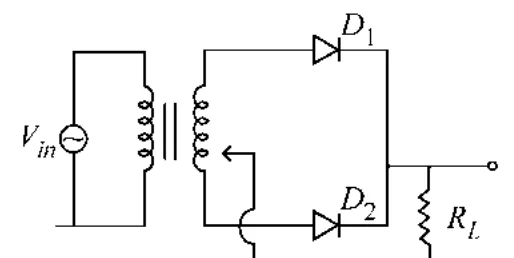
A full wave rectifier circuit with diodes (\(D_1\)) and (\(D_2\)) is shown in the figure. If input supply voltage \(V_{in} = 220\sin(100\pi t)\) volt, then at \(t = 15\) msec
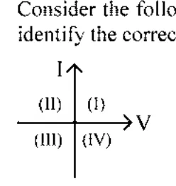
Consider the following statements A and B and identify the correct answer :
A. For a solar-cell, the I-V characteristics lies in the IV quadrant of the given graph.
B. In a reverse biased \(pn\) junction diode, the current measured in (\(\mu A\)), is due to majority charge carriers.
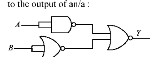
The output (\(Y\)) of the given logic gate is similar to the output of an/a :
A logic circuit provides the output \(Y\) as per the following truth table :
| A | B | Y |
|---|---|---|
| 0 | 0 | 1 |
| 0 | 1 | 0 |
| 1 | 0 | 1 |
| 1 | 1 | 0 |
The expression for the output \(Y\) is :
A full wave rectifier circuit consists of two p-n junction diodes, a centre-tapped transformer, capacitor and a load resistance. Which of these components remove the ac ripple from the rectified output?
Given below are two statements:
Statement I : Photovoltaic devices can convert optical radiation into electricity.
Statement II : Zener diode is designed to operate under reverse bias in breakdown region.
In the light of the above statements, choose the most appropriate answer from the options given below :
For the following logic circuit, the truth table is:
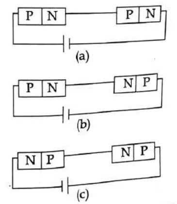
In the given circuits (a), (b) and (c), the potential drop across the two p-n junctions are equal in :
In half wave rectification, if the input frequency is 60 Hz, then the output frequency would be :
The truth table for the given logic circuit is :
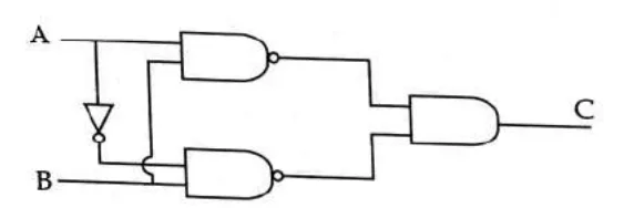
Consider the following statements (A) and (B) and identify the correct answer.
(A) A zener diode is connected in reverse bias, when used as a voltage regulator.
(B) The potential barrier of p-n junction lies between 0.1 V to 0.3 V.
The electron concentration in an n-type semiconductor is the same as hole concentration in a p-type semiconductor. An external field (electric) is applied across each of them. Compare the currents in them.
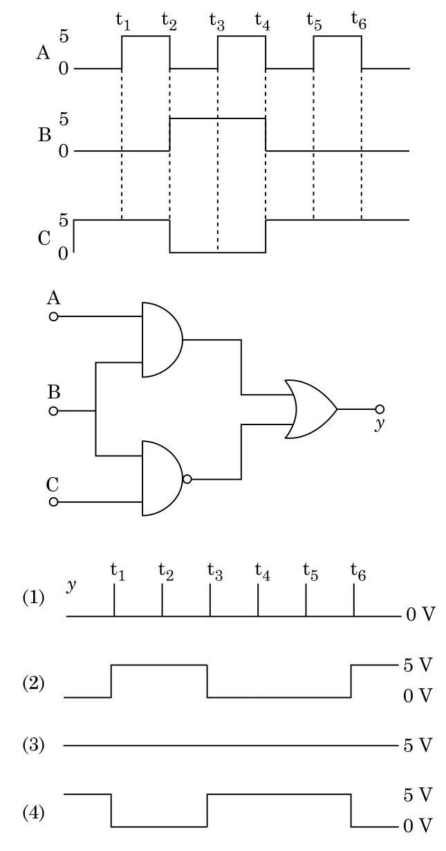
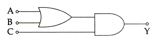
For the given circuit, the input digital signals are applied at the terminals A, B and C. What would be the output at the terminal y ?
The increase in the width of the depletion region in a p-n junction diode is due to :
For transistor action, which of the following statements is correct ?
For the logic circuit shown, the truth table is :
(figure: A and B each pass through a NOT gate; both outputs feed a NOR-type gate (OR gate with output bubble) giving Y)
For a p-type semiconductor, which of the following statements is true ?
The correct Boolean operation represented by the circuit diagram drawn is :
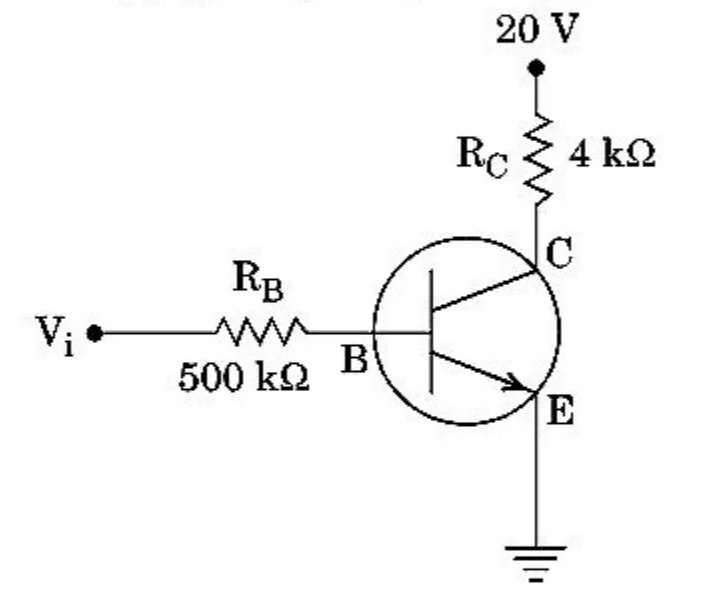
In the circuit shown in the figure, the input voltage V\(_i\) is 20 V, V\(_{BE}\) = 0 and V\(_{CE}\) = 0. The values of I\(_B\), I\(_C\) and \(\beta\) are given by
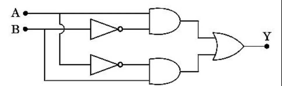
In the combination of the following gates the output Y can be written in terms of inputs A and B as
In a p-n junction diode, change in temperature due to heating
In a common emitter transistor amplifier the audio signal voltage across the collector is 3 V. The resistance of collector is 3 k\(\Omega\). If current gain is 100 and the base resistance is 2 k\(\Omega\), the voltage and power gain of the amplifier is :
The given electrical network is equivalent to :
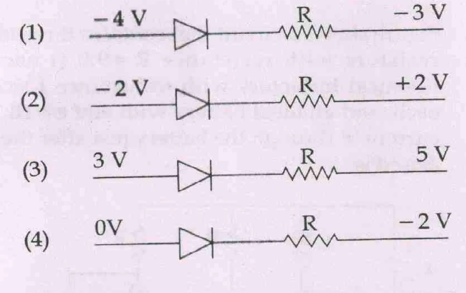
Which one of the following represents forward bias diode ?
Consider the junction diode as ideal. The value of current flowing through AB is :

A npn transistor is connected in common emitter configuration in a given amplifier. A load resistance of 800 \(\Omega\) is connected in the collector circuit and the voltage drop across it is 0.8 V. If the current amplification factor is 0.96 and the input resistance of the circuit is 192 \(\Omega\), the voltage gain and the power gain of the amplifier will respectively be :
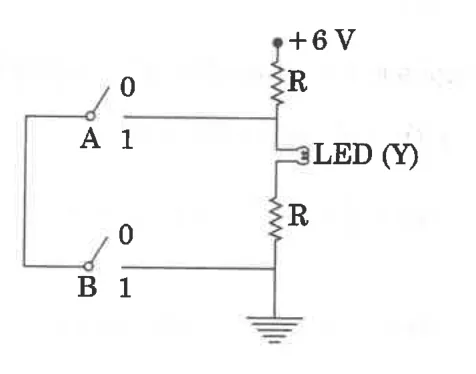
To get output 1 for the following circuit, the correct choice for the input is :
For CE transistor amplifier, the audio signal voltage across the collector resistance of 2 k\(\Omega\) is 4 V. If the current amplification factor of the transistor is 100 and the base resistance is 1 k\(\Omega\), then the input signal voltage is
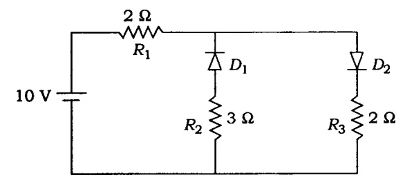
The given circuit has two ideal diodes connected as shown in the figure below. The current flowing through the resistance \(R_1\) will be
What is the output \(Y\) in the following circuit, when all the three inputs \(A, B, C\) are first 0 and then 1?
